Parameters
Enable
On by default.
View
Switch between the final Effect, the Repair Mask view that shows a black and white matte of the area to be repaired or the Fill view that shows the replacement pixels used as fill within the repair mask.
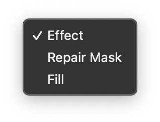
The following options are available:
Zoom
Off by default.
Zoom into the area to be fixed. The HUD is displayed by default.
In FCP and Motion this control is also presented onscreen.

Zoom Level
Set to 30 by default.
The slider is limited to values between 1 and 100 but you can type values between 1 and 1000 by clicking on the current value in the inspector.
Smooth Zoom
Off by default.
Bypass
On by default.
Bypass the Effect.
In FCP and Motion this control is also presented onscreen.
HUD
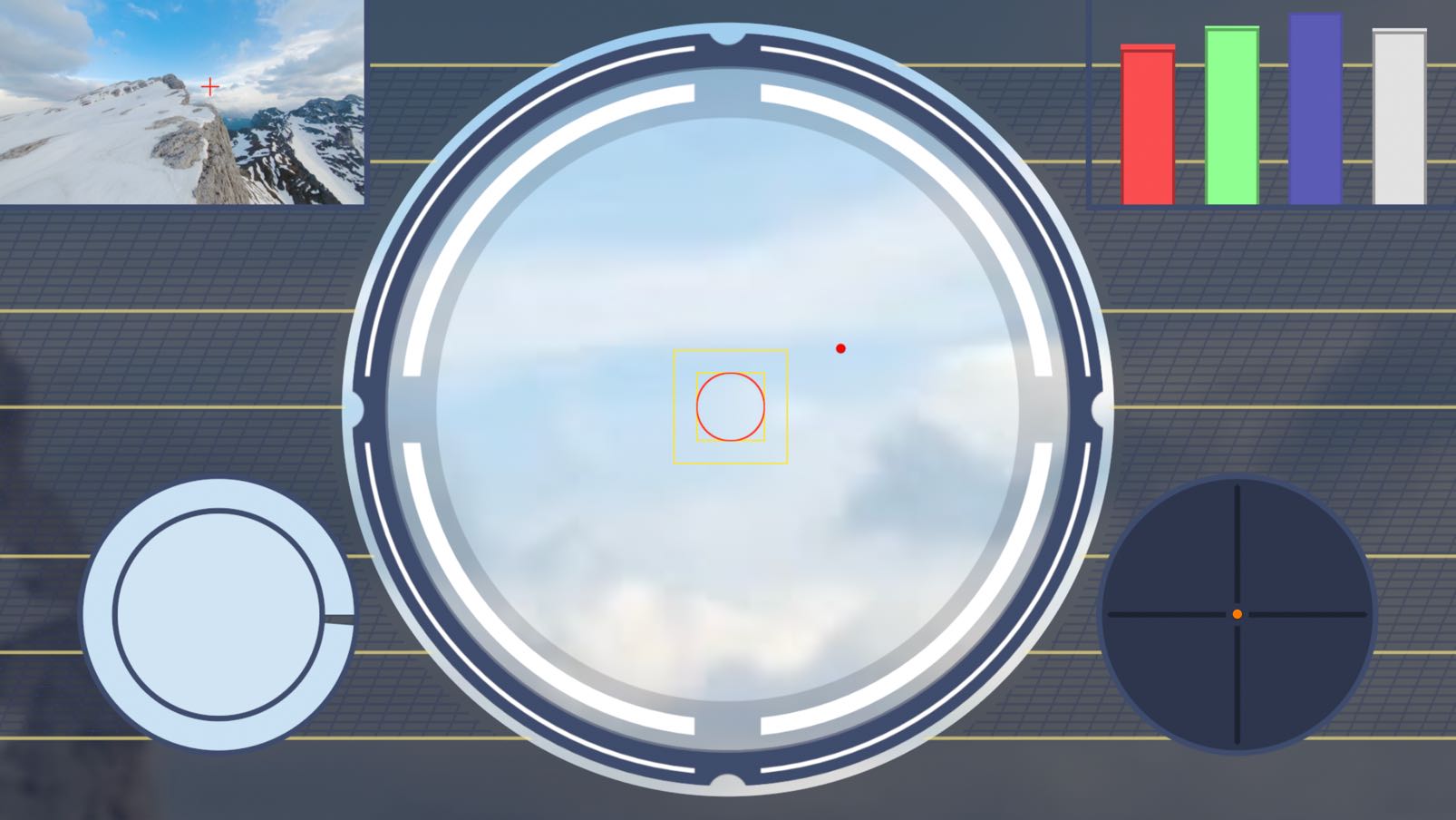
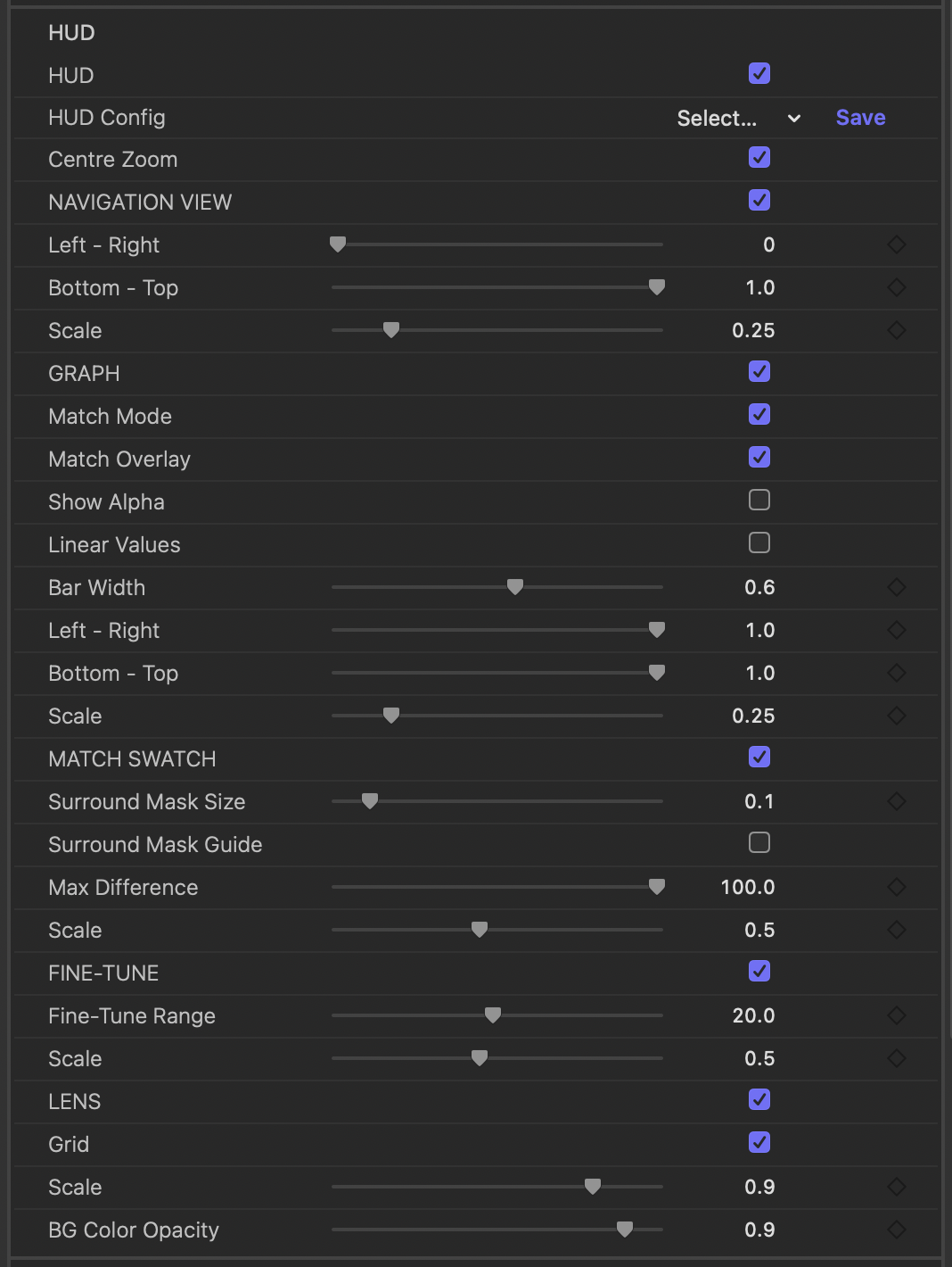
This group contains controls for the onscreen Heads-Up Display of AutoFix. Zoom needs to be enabled for these controls to be available and the HUD visible.
HUD
This group contains controls for the onscreen Heads-Up Display of AutoFix. Zoom needs to be enabled for these controls to be available and the HUD visible.
HUD
On by default.
Enable the Heads-Up Display. Zoom needs to be enabled for the HUD to be shown. Individual elements of the HUD: Navigation View, Graph,Match Swatch, Fine-Tune and Lens can be enabled/disabled below.
In FCP and Motion this control is also presented onscreen.
HUD Config
Presets saved and applied through this parameter affect only to parameters within the HUD group. 2 built-in presets are available.
How do I use the presets popup menu?Centre Zoom
On by default.
NAVIGATION VIEW
On by default.
Left - Right
Set to 0 by default. Only values between 0 and 1 are allowed.
Bottom - Top
Set to 1 by default. Only values between 0 and 1 are allowed.
Scale
Set to 0.25 by default.
The slider is limited to values between 0.1 and 1 but you can type values between 0 and 1 by clicking on the current value in the inspector.
GRAPH
On by default.
Match Mode
On by default.
Match Overlay
On by default.
Show Alpha
Off by default.
Linear Values
Off by default.
Bar Width
Set to 0.6 by default.
The slider is limited to values between 0.1 and 1 but you can type values between 0 and 1 by clicking on the current value in the inspector.
Left - Right
Set to 1 by default.
The slider is limited to values between 0 and 1 but you can type values between -∞ and +∞ by clicking on the current value in the inspector.
Bottom - Top
Set to 1 by default. Only values between 0 and 1 are allowed.
Scale
Set to 0.25 by default.
The slider is limited to values between 0.1 and 1 but you can type values between 0 and 1 by clicking on the current value in the inspector.
MATCH SWATCH
On by default.
The Match Swatch is a handy tool for finding problem areas where the automatic repair might need some finessing. The inner circle shows the average color of the pixels within the repair mask and the outer ring the color of the pixels that surround the mask - the pixels you want to match. The outer ring also doubles as a color difference meter. When the circle is full the colours are identical.
A perfect match won’t necessarily produce the best result but when the match ring is less than around 80% to 90% you probably need to make and keyframe an adjustment.
NB. RGB and luma values of the Match Swatch colors are shown in the Graph - see above.
Surround Mask Size
Set to 0.1 by default.
The slider is limited to values between 0 and 1 but you can type values between 0 and 100 by clicking on the current value in the inspector.
Surround Mask Guide
Off by default.
Shows the outer extent of the pixels used to generate the color of the outer ring of the Match Swatch as a green outline. The inner extent is defined by the edge of the Repair Mask.
NB. The Surround Mask reflects the size and shape of the Repair Mask scaled up depending on the Surround Mask Size setting.
Max Difference
Set to 100 by default.
The slider is limited to values between 10 and 100 but you can type values between 1 and 100 by clicking on the current value in the inspector.
Adjust the maximum difference used by the Match Swatch to set when the outer match ring is at 0%. Decreasing this value will increase the sensitivity of the Match Swatch so that the difference between pixels inside and outside the repair mask will produce greater changes in the percentage of the match ring that is displayed.
Match Swatch uses Delta E (CIE 2000) under the hood and it is the maximum Delta E value that is being set with this slider.
Scale
Set to 0.5 by default.
The slider is limited to values between 0.1 and 1 but you can type values between 0 and 2 by clicking on the current value in the inspector.
FINE-TUNE
On by default.
Fine-Tune Range
Set to 20 by default.
The slider is limited to values between 1 and 40 but you can type values between 1 and 100 by clicking on the current value in the inspector.
Scale
Set to 0.5 by default.
The slider is limited to values between 0.1 and 1 but you can type values between 0 and 2 by clicking on the current value in the inspector.
LENS
On by default.
Grid
On by default.
Scale
Set to 0.9 by default.
The slider is limited to values between 0.5 and 1 but you can type values between 0 and 2 by clicking on the current value in the inspector.
BG Color Opacity
Set to 0.9 by default. Only values between 0 and 1 are allowed.
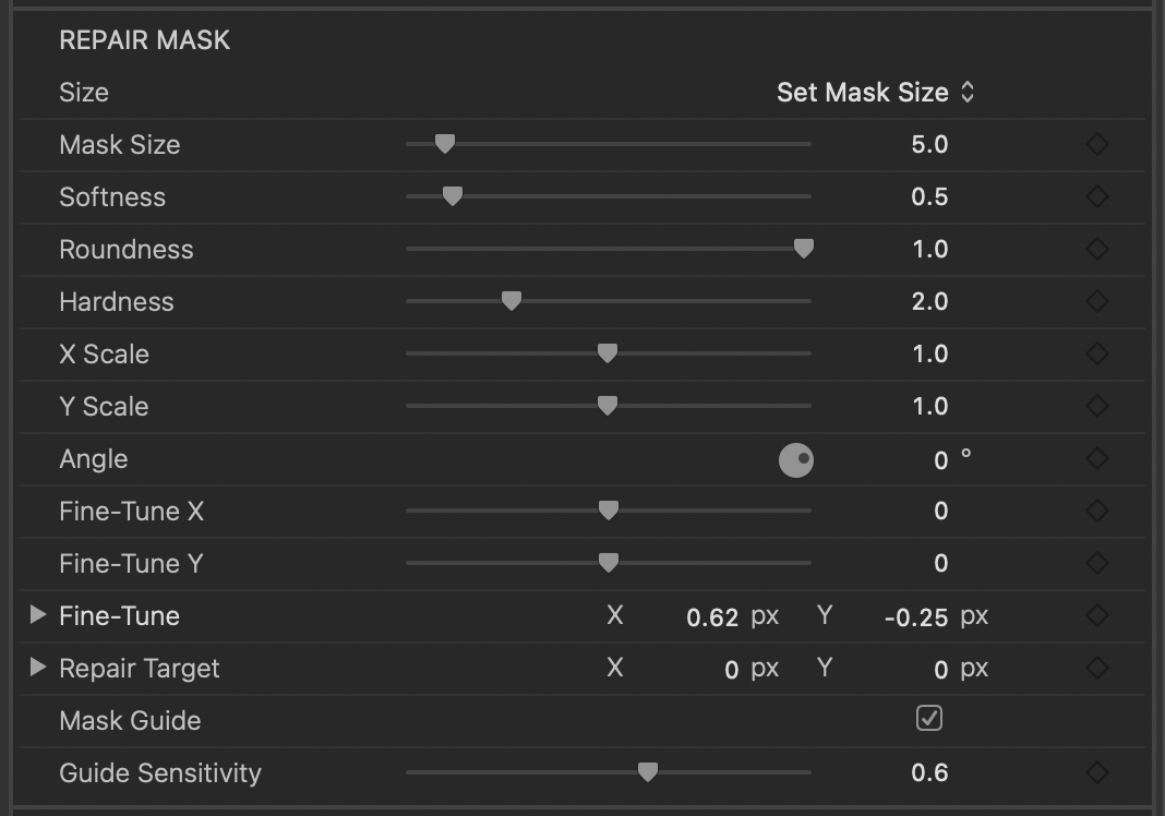
REPAIR MASK
Adjust the mask used to define the area to be repaired. The Mask Guide updates to reflect changes you make in this group as does the Repair Mask view (an option in the View menu).
REPAIR MASK
Adjust the mask used to define the area to be repaired. The Mask Guide updates to reflect changes you make in this group as does the Repair Mask view (an option in the View menu).
Size
The following options are available:
Mask Size
Set to 5 by default.
The slider is limited to values between 1 and 50 but you can type values between 1 and 4000 by clicking on the current value in the inspector.
Softness
Set to 0.5 by default.
The slider is limited to values between 0 and 5 but you can type values between 0 and 100 by clicking on the current value in the inspector.
Roundness
Set to 1 by default. Only values between 0 and 1 are allowed.
Hardness
Set to 2 by default.
The slider is limited to values between 1 and 5 but you can type values between 0 and 100 by clicking on the current value in the inspector.
X Scale
Set to 1 by default.
The slider is limited to values between 0.01 and 2 but you can type values between 0.01 and 10 by clicking on the current value in the inspector.
Y Scale
Set to 1 by default.
The slider is limited to values between 0.01 and 2 but you can type values between 0.01 and 10 by clicking on the current value in the inspector.
Angle
Set to 0° by default.
Fine-Tune X
Set to 0 by default.
The slider is limited to values between -10 and 10 but you can type values between -100 and 100 by clicking on the current value in the inspector.
Fine-Tune Y
Set to 0 by default.
The slider is limited to values between -10 and 10 but you can type values between -100 and 100 by clicking on the current value in the inspector.
Fine-Tune
Repair Target
A point parameter centered in the frame by default.
How do I adjust the location on-screen?
Mask Guide
On by default.
Displays the extent of the Repair Mask as a red outline guide.
In FCP and Motion this control is also presented onscreen.
Guide Sensitivity
Set to 0.6 by default.
The slider is limited to values between 0 and 1 but you can type values between -∞ and +∞ by clicking on the current value in the inspector.
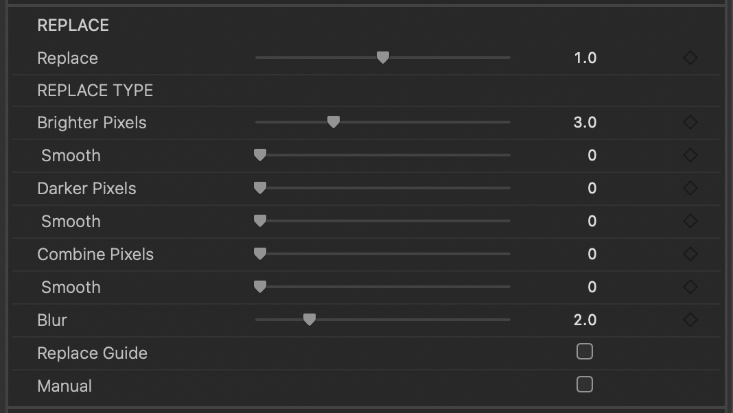
REPLACE
Select and adjust the pixels used to replace the problem area defined by the Repair Mask.
Along with the controls in this group you can control the directional bias of the pixels used for replacement in the Sampling group below.
REPLACE
Select and adjust the pixels used to replace the problem area defined by the Repair Mask.
Along with the controls in this group you can control the directional bias of the pixels used for replacement in the Sampling group below.
Replace
Set to 1 by default.
The slider is limited to values between 0 and 2 but you can type values between 0 and 10 by clicking on the current value in the inspector.
Adjust the pixels used for Replacement. The outer rectangle of the Replace Guide will update. This slider scales all the sliders in the Replace Type section: Brighter Pixels, Brighter Pixels - Smooth, Darker Pixels, Darker Pixels- Smooth, Combine Pixels, Combine Pixels - Smooth.
Moving the Replace slider to zero will bypass the auto correction.
REPLACE TYPE
Brighter Pixels
Set to 3 by default.
The slider is limited to values between 0 and 10 but you can type values between 0 and 1000 by clicking on the current value in the inspector.
Use brighter pixels from the surrounding area to replace the problem pixels. Increasing the slider value will select pixels further away from the edge of the Repair Mask - shown by the outer rectangle of the Replace Guide.
The extent of this operation can be shown by selecting Brighter in the Replace Guide - Type menu within the HUD group.
Smooth
Set to 0 by default.
The slider is limited to values between 0 and 10 but you can type values between 0 and 1000 by clicking on the current value in the inspector.
Brighter Pixels - Smooth: Use the brightest pixel from the surrounding area. Increasing the slider value will include pixels further away from the edge of the Repair Mask. Unlike the standard slider which uses the pixels on the edge of the Sample Guide this slider compares all the pixels within the sample guide and returns the brightest. This will tend to produce smoother results which may work better depending on the shot.
The extent of this operation can be shown by selecting Brighter - Smooth in the Replace Guide - Type menu within the HUD group.
Darker Pixels
Set to 0 by default.
The slider is limited to values between 0 and 10 but you can type values between 0 and 1000 by clicking on the current value in the inspector.
Use darker pixels from the surrounding area to replace the problem pixels. Increasing the slider value will select pixels further away from the edge of the Repair Mask - shown by the outer rectangle of the Replace Guide.
The extent of this operation can be shown by selecting Darker in the Replace Guide - Type menu within the HUD group.
Smooth
Set to 0 by default.
The slider is limited to values between 0 and 10 but you can type values between 0 and 1000 by clicking on the current value in the inspector.
Darker Pixels - Smooth: Use the darkest pixel from the surrounding area. Increasing the slider value will include pixels further away from the edge of the Repair Mask. Unlike the standard slider which uses the pixels on the edge of the Sample Guide this slider compares all the pixels within the sample guide and returns the darkest. This will tend to produce smoother results which may work better depending on the shot.
The extent of this operation can be shown by selecting Darker - Smooth in the Replace Guide - Type menu within the HUD group.
Combine Pixels
Set to 0 by default.
The slider is limited to values between 0 and 10 but you can type values between 0 and 1000 by clicking on the current value in the inspector.
Combines pixels from the surrounding area with the problem pixels. Increasing the slider value will select pixels further away from the edge of the Repair Mask - shown by the outer rectangle of the Replace Guide.
The extent of this operation can be shown by selecting Combine in the Replace Guide - Type menu within the HUD group.
Smooth
Set to 0 by default.
The slider is limited to values between 0 and 10 but you can type values between 0 and 1000 by clicking on the current value in the inspector.
Combine Pixels - Smooth: Combines pixels from the surrounding area with the problem pixels. Increasing the slider value will include pixels further away from the edge of the Repair Mask. Unlike the standard slider which uses the pixels on the edge of the Sample Guide this slider combines all the pixels within the sample guide with the pixels to be repaired. This will tend to produce smoother results which may work better depending on the shot.
The extent of this operation can be shown by selecting Combine - Smooth in the Replace Guide - Type menu within the HUD group.
Blur
Set to 2 by default.
The slider is limited to values between 0 and 10 but you can type values between 0 and 1000 by clicking on the current value in the inspector.
Replace Guide
Off by default.
Enable to show a yellow outline guide of the pixels being used to fill the repair area. The inner rectangle mirrors the repair mask and the outer rectangle shows the extent of the pixels used for replacement. The outer rectangle updates to reflect changes in the Replace sliders.
In FCP and Motion this control is also presented onscreen.
Type
Choose the Replace Type that is used to set extent of the outer rectangle of the Replace Guide.
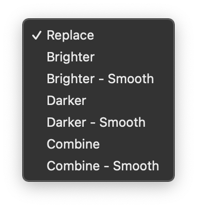
The following options are available:
Manual
Off by default.
Enable to make manual adjustments to the replacement pixels including offset,scale and rotation as well as color controls.
If you are wanting to use the manual controls to clone an area disable the auto correction by taking the Replace slider to zero and zero the blur slider as well.
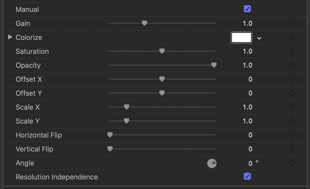
Gain
Set to 1 by default.
The slider is limited to values between 0 and 3 but you can type values between 0 and 100 by clicking on the current value in the inspector.
Colorize
Saturation
Set to 1 by default.
The slider is limited to values between 0 and 2 but you can type values between 0 and 10 by clicking on the current value in the inspector.
Opacity
Set to 1 by default.
The slider is limited to values between 0 and 1 but you can type values between -∞ and +∞ by clicking on the current value in the inspector.
Offset X
Set to 0 by default.
The slider is limited to values between -50 and 50 but you can type values between -4000 and 4000 by clicking on the current value in the inspector.
Offset Y
Set to 0 by default.
The slider is limited to values between -20 and 20 but you can type values between -4000 and 4000 by clicking on the current value in the inspector.
Scale X
Set to 1 by default.
The slider is limited to values between 0.25 and 5 but you can type values between 0 and 100 by clicking on the current value in the inspector.
Scale Y
Set to 1 by default.
The slider is limited to values between 0.25 and 5 but you can type values between 0 and 100 by clicking on the current value in the inspector.
Horizontal Flip
Set to 0 by default. Only values between 0 and 1 are allowed.
Horizontally flip the pixels used to replace the problem area.
This control is provided as a slider (that can be set to 0 or 1) rather than a checkbox so that it can be keyframed.
Vertical Flip
Set to 0 by default. Only values between 0 and 1 are allowed.
Vertically flip the pixels used to replace the problem area.
This control is provided as a slider (that can be set to 0 or 1) rather than a checkbox so that it can be keyframed.
Angle
Set to 0° by default.
Resolution Independence
On by default.
Change the extent of the pixels set by the Replace and Replace Type sliders depending on the frame size.
Disable to use absolute pixel values at all frame sizes.
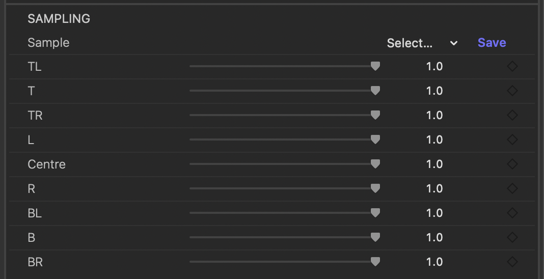
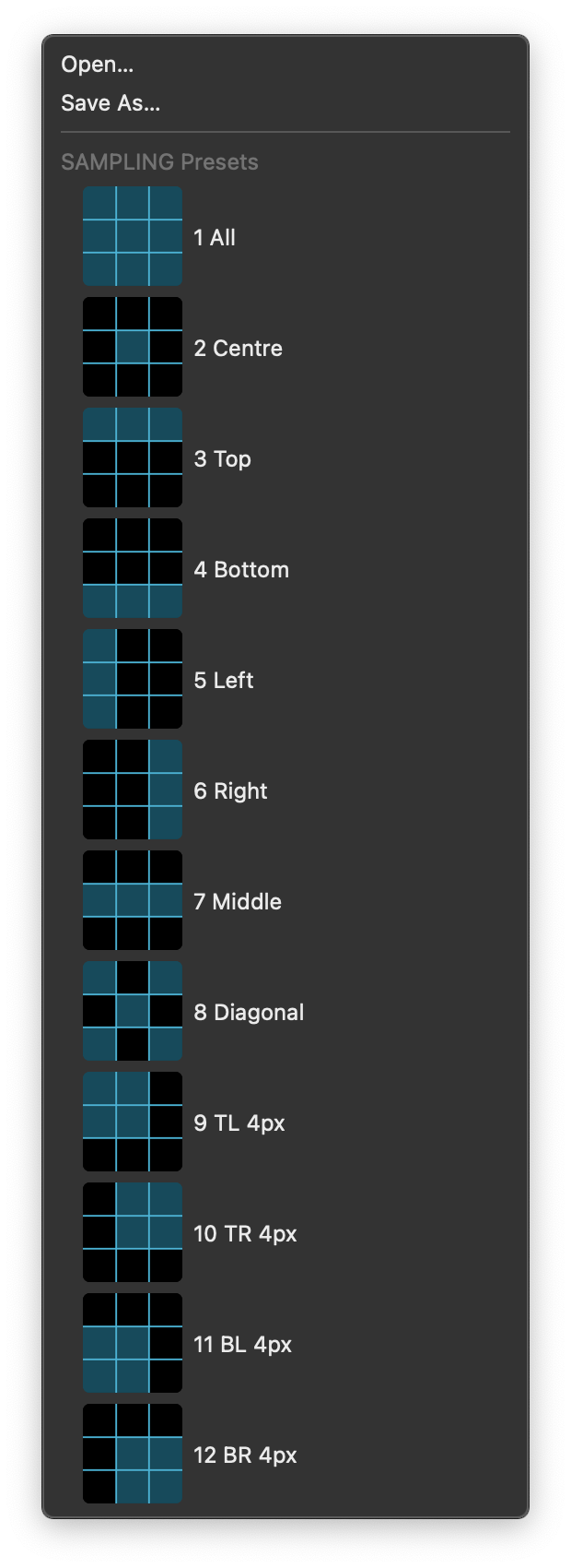
SAMPLING
Adjust the directional bias of the pixels used for replacement. Use to exclude pixels you don’t want to use to replace the problem pixels. For example to exclude one side of an edge between dark and light pixels. Select one of the built-in presets or refine the area sampled with the sliders.
Sample
Presets saved and applied through this parameter affect only to parameters within the SAMPLING group. 12 built-in presets are available.
How do I use the presets popup menu?Use one of the built-in sample presets or save your own for later use after adjusting the sliders in the Sampling group.
In FCP and Motion this control is also presented onscreen.
TL
Set to 1 by default.
The slider is limited to values between 0 and 1 but you can type values between 0 and 2 by clicking on the current value in the inspector.
T
Set to 1 by default.
The slider is limited to values between 0 and 1 but you can type values between 0 and 2 by clicking on the current value in the inspector.
TR
Set to 1 by default.
The slider is limited to values between 0 and 1 but you can type values between 0 and 2 by clicking on the current value in the inspector.
L
Set to 1 by default.
The slider is limited to values between 0 and 1 but you can type values between 0 and 2 by clicking on the current value in the inspector.
Centre
Set to 1 by default.
The slider is limited to values between 0 and 1 but you can type values between 0 and 2 by clicking on the current value in the inspector.
R
Set to 1 by default.
The slider is limited to values between 0 and 1 but you can type values between 0 and 2 by clicking on the current value in the inspector.
BL
Set to 1 by default.
The slider is limited to values between 0 and 1 but you can type values between 0 and 2 by clicking on the current value in the inspector.
B
Set to 1 by default.
The slider is limited to values between 0 and 1 but you can type values between 0 and 2 by clicking on the current value in the inspector.
BR
Set to 1 by default.
The slider is limited to values between 0 and 1 but you can type values between 0 and 2 by clicking on the current value in the inspector.
Presets
Presets contain a snapshot of your effect configuration. While no built-in presets are available, you can still save and load your own preset files.
When you save parameter configuration to a file on disk, this file can later be loaded to recreate the same effect configuration. Presets generated in one video application can be used by the same plug-in running in a different video application.
How do I use the presets popup menu?